Credits: Biovision-Infonet
Root-knot nematodes

(c) University of Hawaii, www.ctahr.hawaii.edu/nelsons
Cutworms

(c) A.M. Varela, icipe
African Armyworm

(c) University of Arkansas
Portal for the icow Apps content
Credits: Biovision-Infonet
Credits: Biovision-Infonet

Scientific Name: Daucus carota
Order / Family: Araliales: Apiaceae
Pests & Diseases: African armyworm, Bacterial soft rot, Cottony soft rot, Cutworms, Damping-off diseases, Leaf blight, Powdery mildew, Root-knot nematodes

Carrot is a popular vegetable with high vitamin A content, grown in East Africa mostly in the cooler highlands.
The roots are consumed raw or cooked, alone or in combination with other vegetables (for example, peas), as an ingredient of soups, sauces and in dietary compositions.
Young leaves are sometimes eaten raw or used as fodder.
Carrots are an important source of vitamin A in human diets.
Vitamin A deficiency can lead to blindness and especially for children to a greater risk of dying from ailments such as measles, diarrhoea or malaria.
Carrots can grow under a range of climatic conditions, but they perform best under moderate temperatures.
They are mostly cultivated as a cool season crop. Seed germination occurs between 7degC and 30degC. Optimum air temperatures are 16-24degC. Soil temperatures above 25degC may reduce root quality, including root colour.
High temperatures can cause burning of young seedlings. For economic yields, carrots should be grown in tropical regions at altitudes above 700 m. Early-maturing carrot cultivars may grow in the lowlands, but yields will be low and roots will have a poor colour.
Carrots grow best in a well-drained friable loam free of stones and hard soil clods. It is a short season crop of 2-3 months with the potential of high yields for family food security and fresh market sales.
It does well in the cooler areas of Kenya under both rainfed and irrigated conditions.
Carrots are propagated by seeds. Seeds are sown, often mixed with sand, 1/2 – 1 cm deep in drills 10-15 cm apart in finely prepared soils previously cultivated to a depth of at least 30 cm.
Lightly aerate the soil by shallow digging before sowing carrots or sow them in ridge culture (small dams of 10 to 20 cm height) to facilitate mechanical weeding, thinning, and to limit soil borne diseases.
In addition, this will allow easier penetration by the carrot root and will also improve water holding capacity.
Seedlings are thinned to 5-8 cm in the rows. Seed requirements (200 plants/m2 and 70% germination) for the dominant half-long carrot cultivars used in Asia, are 4-5 kg/ha.
For bigger carrots, the density may be reduced to about 100 plants/m2.
| “Chantenay” | Fresh market and canning |
| “Nantes” | Fresh market |
| “Amsterdam forcing” | Fresh market variety |
| “Little finger” | Suitable for canning |
| “Nebula F1” | Fresh market |
| “Touchon” | Fresh market |
Carrots that bolt (produce seed) in between normal carrots should be pulled out and fed to livestock.
Seed produced this way will not produce good quality carrots.
Seed production under tropical highland (above 1200 m) conditions is possible by selecting and harvesting the best quality mature carrot roots and replanting them separately in a corner of the field.
Bolting and seed setting soon follows.
Crop rotation is essential to reduce soil-borne diseases and pests. Mulching (rice straw or dried grass) after sowing is recommended to encourage germination. Seedlings may be earthed-up when roots start swelling to keep them cool and prevent green tops.
Temperature of 15 to 20degC is optimal for seed development. In hot weather, light overhead shade is beneficial. Under such conditions carrots grow well under the canopy of fruit trees.
Irrigation during dry spells is necessary to prevent irregular root development. Nutrient requirements of carrots are particularly high for potassium (200-300 kg/ha) and low to medium for nitrogen (0-90 kg/ha). Carrots are sensitive to high Chlorine concentrations and more susceptible to diseases at very high soil pH.
Liming is recommended when pH is below 5.5. Well-decomposed organic manures are beneficial when applied moderately (10-20 t/ha).
Fresh organic matter such as farmyard manure or manure from a leguminous crop can induce forked roots, which are difficult to clean and to market.
Young carrot seedlings are weak and grow slowly. Therefore, it is essential to keep weeds under control for the first few weeks after germination. Cultivate shallowly with a hoe.
Deep cultivation may injure the roots. Weeding and thinning of young plants can be very labour intensive, for which reason most families grow fairly small beds at any one time.
Because of their limited space requirements and early growing habits, carrots are ideal for intercropping between other crops such as tomatoes, lettuce or capsicums and because of their fragrant leaves can help keep pest levels low.
Other crops good for intercropping with carrots include garlic, dwarf bean, onion, parsnip, leek, small peas, pea mange-tout (snow peas), and radish. The most profitable example of an association is that of carrots and leeks.
Carrots have very deep roots that extract nutrients deep in the soil, whereas leeks have extremely superficial roots, which help the crop to extract nutrients near the soil surface.
Moreover, carrots can drive away worms from leeks, while leeks can drive away flies from the carrots (TOF No. 8, page 8).
Carrots are mostly harvested manually by pulling up the roots at the leaves as long as the soil is moist and soft.
If the soil has dried, it will be necessary to use either a spade or similar tool to loosen the soil and harvest the roots. Carrots are usually ready for harvesting 60-85 days after sowing.
Mature roots should be orange-coloured internally down to the blunt tip.
A good market price can be fetched from young carrots with a fresh top, but leaving the top on dries out the root quickly and reduces the marketing period of the crop.
An alternative is to trim the top back to about 2 cm and package attractively.
For mature carrots the tops are trimmed down completely to avoid storage rots before marketing.
Carrots can remain in good condition for 100-150 days when the foliage is removed and they are stored at 1-4deg C with 95-100% relative humidity.
Carrots should be stored separately from other vegetables to prevent a bitter flavour induced by ethylene (a colourless gas with a sweet odour that is produced by many fruits and vegetables that accelerates the ripening process).
Generally carrots store better when they are mature and harvested under moist conditions, and undamaged and free of diseases and pests.
Credits: Biovision-Infonet
Credits: Biovision-Infonet

Shallow ground water is rainwater that has percolated into the underground and can be reached by means of hand dug wells.
Ground water is rainwater that has percolated into the underground. There are two main types of ground water, namely:
1) Shallow ground water that can be reached by means of hand dug wells in areas where rainwater has been trapped in the underground such as in valleys, downstream of earth dams and near swamps, seasonal water courses, rivers and lakes.
2) Deep ground water is rainwater that has percolated deep into the underground during centuries or thousands of years.
This water source can only be reached by drilling deep boreholes from where water is extracted using electric powered submersible pumps that deliver water to storage tanks.
Recharge of rainwater to deep boreholes may take hundreds of years. Most deep boreholes do therefore suffer from sinking water levels or high salinity of the water before they finally may run dry.
Due to these constraints and the high cost of construction, operation and maintenance of deep boreholes, this subject is not considered relevant for this website.
Often shallow ground water can be found in valleys, downstream of earth dams, along seasonal water courses, rivers and near swamps and lakes.
Water for domestic use watering livestock and garden irrigation can be drawn from hand dug wells sunk in shallow ground water.
Hand drilled boreholes using a simple drilling rig can also be used for reaching shallow ground water.
Sinking of shallow wells is the most economical solution to construct a good water supply for homesteads and communities, provided fresh ground water can be found within a depth of maximum 20 metres.
Shallow water may be found in the following locations:
Since time immemorial, riverbeds have provided water for people and animals.
During extreme droughts, when all other water sources have dried up, water can still be found in riverbeds.
Elephants, ant-eaters and some other wild animals have a special sense by which they can locate such places where water is found. Some rural people and most well-diggers also know that water can only be found at certain places.
They may also give a rough estimate on how deep they have to dig before reaching the water-table.
Their knowledge is based on the fact that certain species of trees and vegetation must have roots reaching down and into the water-table in order to survive droughts.
This traditional information is compiled in the table below.
Techniques for identifying places with shallow water tables are:
| Botanical name | Kiswahili & Kikamba names | Depth to water level |
| Cyperus rotundus | Kiindiu | 3 to 7 m |
| Vangueria tomentosa | Muiru Kikomoa | 5 to 10 m |
| Delonix elata | Mwangi | 5 to 10 m |
| Grewia | Itiliku Itiliku | 7 to 10 m |
| Markhamia hildebrandtii | Muu Chyoo | 8 to 15 m |
| Hyphaene thebacia | Kikoko Ilala | 9 to 15 m |
| Borassus flabellierfer | Mvumo Kyatha | 9 to 15 m |
| Ficus walkefieldii | Mombu | 9 to 15 m |
| Ficus natalensis | Muumo Muumo | 9 to 15 m |
| Ficus malatocapra | Mkuyu Mukuyu | 9 to 15 m |
| Piptadenia hildebranditi | Mganga Mukami | 9 to 20 m |
| Kigelia aethiopica | Mvungunya Muatini | 9 to 20 m |
| Acacia seyal | Mgunga Munini | 9 to 20 m |
Since the above mentioned trees must have their tap root in the water table, the depth of a water-table can be found by knowing the depth of the tree’s tap root.
A rule of thumb states that the tap root of a tree has a depth equal to about 3/4 of the height of the tree.
The height of a tree can be found by measuring the length of the shadow the tree is casting on the ground and comparing it with the length of the shadow of a stick 100 centimeters long.
The two measurements should be taken in the sunshine of early morning or late afternoon when the shadows are longest.

For example: If the stick’s shadow is 80 cm long, the ratio is: 100/80 = 5/4 If the tree’s shadow is 12 m long, then the tree is: 12 m x 5/4= 15 m high and the tap root and water level is at: 15 m x 3/4 = 11.25 m depth.

The floors under the sand in riverbeds can consist of soil, clay, murram, black cotton soil, boulders, fractured rocks or solid rock bars
Where floors consist of permeable (water-leaking) material, such as sandy soil, fractured rocks or large boulders, water will seep into the underground through the floor.
This may be beneficial for deep boreholes but certainly not for extracting water from riverbeds.If a floor consists of an impermeable (water-tight) texture, such as clay, clayey soil or murram, there is no leakage through the floor.
Water can therefore be extracted from the riverbed, unless it has drained downstream and left the riverbed dry.
Riverbeds have downstream gradients because they function as drainage channels for rainwater run-off.
Water in riverbeds is therefore always moving downstream on the surface and between the sand particles under the surface of riverbeds. Surface flow of water can easily be observed during floods but the subsurface flow can only be observed when water is scooped out of waterholes.
The reason why some riverbeds have water and others have not, is because the former have impermeable floors. If riverbeds have impermeable floors but no water, it is because the water has been drained downstream by gravity.
If riverbeds with impermeable floors have water, then something must have stopped the water from being drained downstream. What could that be? The answer is found by hammering iron rods into the sand of riverbeds at certain intervals.
Such probing shows that most riverbeds have a floor under the sand that bulges up and down. These natural barriers, called dykes, give the answer.Where the floor bulges upwards it acts as an underground dyke that stops the underground flow of water, as seen on probing points no. 10, 13, 15, 19 and 23.
Where there is a depression in the floor it accumulates water, as seen on probing points no. 9, 14, 16 and 21. These are subsurface water reservoirs in the sand, from where water can be extracted.
Water is found in this waterhole because the dyke prevents the water seeping downwards in the voids between the sand in the riverbed.

Gifted persons can use dowsing to locate underground water sources and underground dykes. The tool consists of a 1m long brazing rod cut in two halves and each half having a 12 cm long handle.


How to do: Hold the two dowsing rods loosely and pointing downwards so that they can swing freely. However, the hands must be held steady to allow gravity to pull the rods down while they are parallel.
When walking slowly over an unknown underground water source, the rods will swing inwards. The force of the pull indicates the depth and volume of water in the ground.
Only certain people have the ability to detect water in this way. Left: here is water; Right: here is no water.

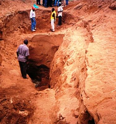
When the most promising lengths of a riverbed have been identified during an evaluation walk, they are probed using probing rods hammered into the sand. The probing data is used for:
a) Drawing a plan and profiles of the riverbed to identify the deepest place from which water should be extracted and the shallowest place where the wall for a subsurface dam, a weir or a sand dam can be constructed.
b) Estimating the volume of sand in the reservoir and the extractable volume of water from the sand.
c) Providing the required data for drawing the designs and estimating the costs of construction.

Trial pits are excavated down to the floor under the sand every three metres to confirm the correctness of the probing.
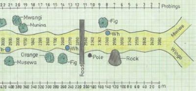
Plans and profiles of riverbeds are very useful for identifying places with shallow water tables and volume of extractable water from riverbeds. See for example the plan and longitudinal profile of Mwiwe riverbed.
A plan and a longitudinal profile was drawn according to the probing data on a sheet of A3 mm graph paper which is 40 cm long and 28 cm wide.
The horizontal measurements were drawn to a scale 1:2000, which means that the 440 metres length of the riverbed was drawn as 22 centimetres long and the 20 metre intervals between the probings were drawn as 1 centimetre long on the graph papers.

The plan shows that the probed river has a length of 440 m and width varying from 17.5 m to 33.0 m. Water-indicating trees, e.g. Figs, Mwangi and Munina, grow along the riverbed.
Waterholes having water 7 months after the last rains were located at probing point No. 10, 14 and 21 where the sand is deep.
Water is trapped in the sand by downstream dykes at points No. 11, 18 and 23, as see on the longitudinal profile on the right.
The longitudinal profile shows that the sand is 3.0 m deep at point No. 14 and 1.75 m deep at point No. 21.
Since both places are holding water 7 months after the last rain they are the best extraction points in that part of Mwiwe riverbed.
The next phase in surveying the riverbed was to probe across at point No. 17 in order to learn of the volume of the depression and its water yielding capacity.
When dry riverbeds are flooded by rains and flash-floods, the air in the voids between sand particles is pressed out by the water because water is heavier than air.
When a dry riverbed is being flooded, it looks as if the riverbed is boiling as tens of thousands of air bubbles are being pressed out of the sand. This process is known as saturation.
Fine textured sand has tiny voids that get saturated slowly with water. About 10% of water can be extracted from the volume of fine sand.
Coarse sand has larger voids and is therefore saturated much quicker than fine sand. The volume of water that can be extracted from coarse sand is about 35% of the volume of sand.
Silt and sand extractability was tested and classified as follows:
| Silt | Fine Sand | Medium Sand | Coarse Sand | |
| Size (mm) | < 0.5 | 0.5 to 1 | 1.0 to 1.5 | 1.5 to 5.0 |
| Saturation | 38% | 40% | 41% | 45% |
| Water Extraction | 5% | 19% | 25% | 35% |

The porosity and the volume of water that can be extracted from the sand reservoir can be determined by saturating 20 litres of sand with a measured volume of water.
The water is then drained out of the container and measured by removing a plug from the bottom of the container.
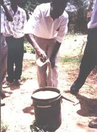
1) Take samples of dry sand and fill in a 20 litres container.
2) Add water until saturation. For example: If the saturation of the sand was reached after adding 8 litres of water, the saturation is 40% (8 / 20 x 100)
3) Then make a small hole in the bottom of the container to drain the water out of the sand. If, for example, in one hour, 5 litres of water were extracted from the sand, that gives an extractable capacity of 25% (5 / 20 x 100).
The oldest subsurface dams known were constructed in the almost waterless area around Dodoma, in the Tanganyika and now Tanzania, when the railway was built around 1905. The purpose of the subsurface dams was to provide water for the steam locomotives which they successfully did for many decades.
A subsurface dam was built of soil and documented by Bihawana Mission near Dodoma in the early 1950s and is still functioning well. A similarly successful subsurface dam was built in the same area in the 1920s. Several subsurface dams were built of various materials, such as soil, burnt bricks, concrete blocks and reinforced concrete during a training course in 1991.
Should the water yield from a river intake or well be insufficient for the demand, then a subsurface dam can be constructed cheaply of soil. The function of a subsurface dam is:
a) Block the underground flow of water between the voids in the sand
b) Raise the water level in the sand to about 50 cm below the surface of a riverbed.

In order to get a maximum volume of water for a minimum of work and investment, the walls of subsurface dams, weirs and sand dams should, whenever possible, always be constructed on underground dykes that are situated downstream of underground water reservoirs, identified by waterholes, water-indicating vegetation, dowsing and probing.
When a suitable site has been identified in a riverbed, the most clayey soil for construction of the dam wall has to be found.
1) Collect soil samples from nearby riverbanks and fields. The equipment for analyzing the soil samples consists of plastic bottles of equal size, of which the caps have been removed and the bottoms cut off.
2) The bottles are placed upside down in the sand, or sloping against a wall, and filled halfway with soil samples.
3) Water is poured on top of the soil samples several times. After some minutes it can be observed which soil sample has the slowest infiltration rate due to having the highest clay content. This soil is the most suitable for building the dam wall.

When a suitable site has been identified, all the sand in the riverbed is removed in a 3 metre wide stretch between the two riverbanks, so that the floor under the sand is fully exposed.
Thereafter a 100 cm wide trench, called a key, is excavated into the floor right across the riverbed and into the two riverbanks. The depth of the key must be at least 60 cm into solid soil to prevent seepage under the dam wall.
The best clayey soil identified by the testing mentioned above, must now be transported to the dam site by e.g. sacks, donkeys, ox-carts, wheelbarrows or a tractor with trailer.
First the whole length of the key is filled with a 20 cm thick layer of the clayey soil that is moistened with water and compacted using either tree trunks or cows or a tractor driven back and forth until all air is forced out of the soil.
Thereafter, successive 20 cm thick layers of soil are laid out along the whole length of the key and dam wall, and each layer is moistened and compacted, until the top of the dam wall has reached to 30 cm below the surface of the sand in the riverbed.
The upstream and downstream sides of the dam wall, having a slope of about 45 degrees, are then smoothened using shovels and wooden floats. The upstream side of the dam wall should be plastered with clay or cow dung to prevent water from seeping through the dam wall.
Finally, the excavated sand is back-filled against both sides and the top of the dam wall. Two short iron bars should be hammered into the riverbanks at each end of the dam wall, to locate the dam wall in the future (the dam will be invisible after the first flooding).


There are several technologies for lifting water from riverbeds that are affordable and sustainable for individuals and community water projects.
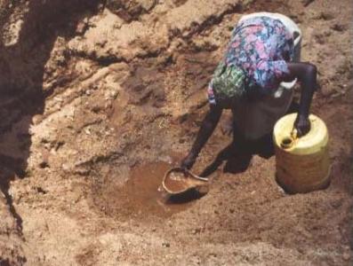
The oldest and simplest method is to dig a waterhole in a riverbed and use a calabash cut in half to scoop water into a calabash or a jerry can.

A safer and cleaner option is to sink a hand-dug well next to the waterhole in a riverbed. However this option is more expensive.
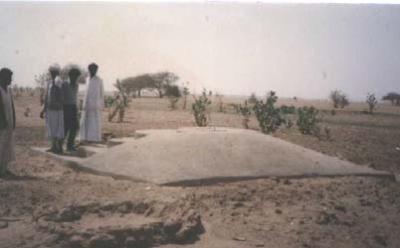
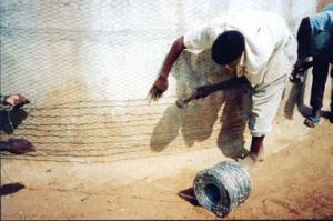
Hand-dug wells situated in riverbeds must be equipped with a well-head to prevent the well shaft being filled with sand during floods such as this hydro-dynamic well-head used in Sudan.
It is shaped as a wedge to break the force of floods.


A well-shaft can also be lined with worn-out lorry tyres and closed by a lid made from the bottom of an oil-drum as in Somaliland.
Although sinking of wells directly into riverbeds is the cheapest way to extract water, the wells might be damaged by unusually large flash-floods.
It is therefore safer to build hand-dug wells on the riverbanks and draw water from there provided the underground soil is sandy soil that allows water to seep into the hand-dug wells.

If underground water cannot seep into a hand-dug well, an infiltration pipe can be laid in a trench to drain water into the hand-dug well.
The design can be made cheaper by filling the trench with stones covered with polythene sheeting instead of laying the infiltration pipe.
Infiltration pipes can also be installed in a hole drilled buy a jet of water form a length of steel pipe connected to petrol powered pump with a flexible hose pipe.
Well shafts can be lined with burnt bricks when built upwards from the bottom of hand-dug wells. However, this procedure is risky because collapsing soil can bury the builders alive.
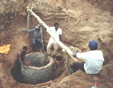
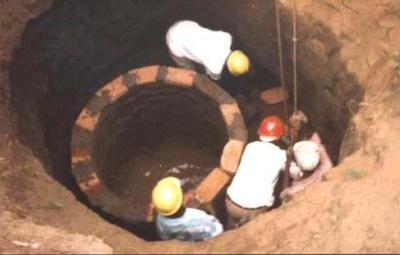
A safer method is to build a sinking well whereby curved concrete blocks are reinforced together onto a foundation ring made of concrete. The foundation ring is built in the excavation for the well.
Then sand is removed from the inside of the shaft causing it to sink into the sand. When the top of the shaft has sunk to ground level, more blocks are added onto the shaft. Sand is then removed and the shaft sinks.
The procedure is repeated until the shaft has reached its final depth.Concrete culverts can be sunk in a similar way but they are more difficult to handle due to their weight.
To ensure inflow of water to a well, U-bend insulated wires can be laid in the lower course of the well shaft.
When the shaft has been sunk to its final depth, the wires are pulled and, thereby leaving many small holes through which water can seep into the well.
The cost of lining well shafts can be reduced by placing a large perforated PVC pipe in the centre of the excavation and filling stones and gravel all around it up to the ground level.
The simplest and cheapest method to lift water is a bucket tied to a rope.


The pump in the pump house above is a booster pump, with a capacity of 19m3/hr at 154 m head.


Credits: Biovision-Infonet
Credits: Biovision-Infonet

Surface water is rainwater running off from land surfaces into rivers, lakes and seas which can be collected, stored and utilized through rainwater harvesting.
Surface water is rainwater running off from land surfaces into rivers, lakes and seas which can be collected, stored and utilized by a technique called rainwater harvesting.
To the surface water structures to collect and store water belong ponds and earth dams such as Charco dams, Hillside Dams and Valley dams.
The type of pond, or earth dam, to be constructed for homesteads depends on the type of landscape available for the construction as follows:
1) Charco Dam is suitable for flat land, preferable with a road catchment to supply rainwater run-off.
2) Hillside Dam is the best option for slightly sloping land in places where rainwater flows.
3) Valley Dam can be built in valleys flooded with low floods from small catchments. Although this type of dam is the most cost efficient, it is also the type most easily damaged or washed away by floods if it is not properly designed and constructed.
Charco and Hillside dams are preferably built in circular and oval designs because:
1) They give maximum storage volume for minimum works.
2) The internal and external pressures are evenly distributed and this prevents cave-in of the soil in the walls of the water reservoir.
3) In sandy soils, they can be lined successfully with clayey soil, because the shapes do not have any corners.

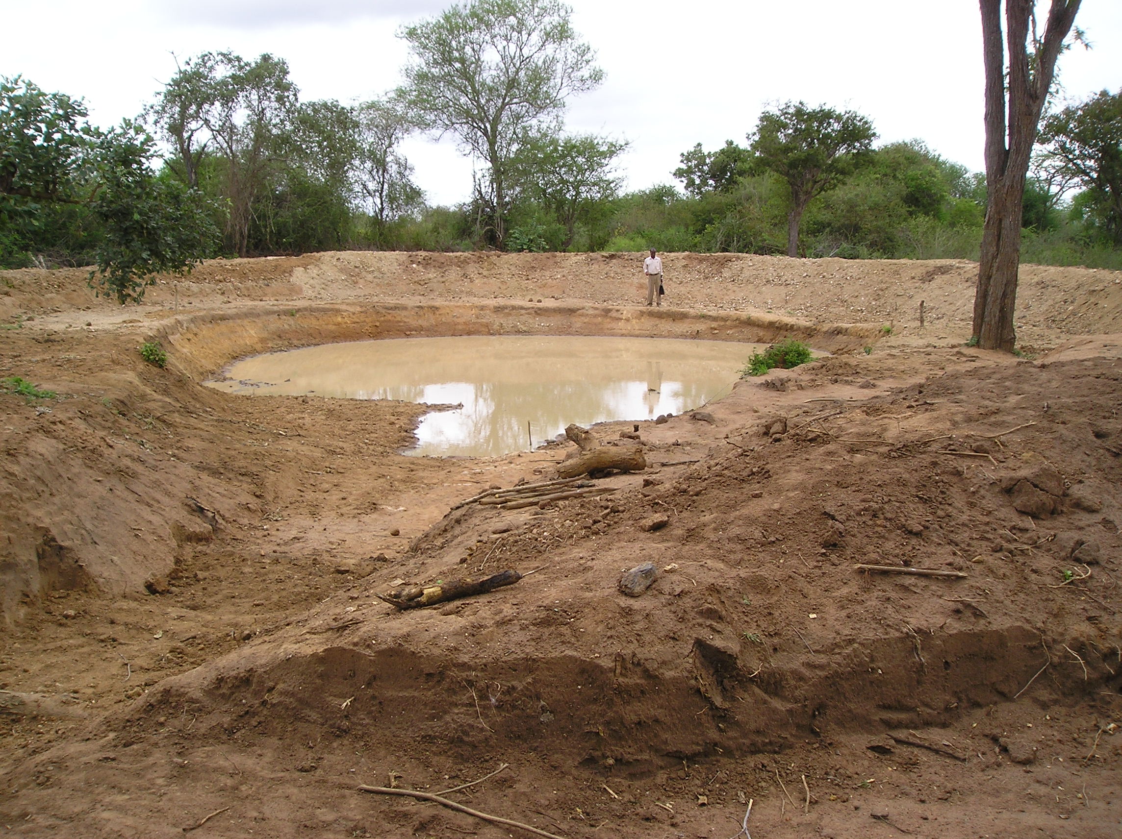
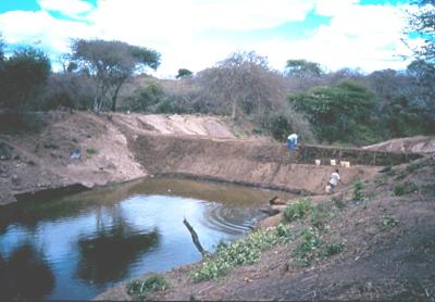
Farmers and cattle owners in semi arid parts of Tanzania build small earth dams known as Charco, or Milambo in Kiswahili.
These dams are built in a way, which tries to reduce evaporation losses by deepening the water reservoirs and minimising their surface area.
Trees and shrubs are grown on the windy site of the charco dams to function as windbreaks and reduce evaporation.
The best sites for constructing charco dams are in natural depressions where rainwater either flows or accumulates during rainy seasons.
The soil should, preferably, be deep clay, silt or Black Cotton Soil. Coarse textured sandy soils should be avoided as these are highly permeable and water will drain through them.
If seepage is high in charco dams, they can be plastered with clayey soil and compacted using compactors made of tree trunks.
Sites with underlying strata of sand, gravel, limestone or fractured rock at a shallow depth may also result in high seepage losses, unless they are sealed with clayey soil.
Ideally, a charco dam should be located near to a gully or a natural waterway, which carries water during and after rainfalls, as this water can easily be diverted into the dam.
Avoid building dams near or downstream from livestock enclosures to avoid organic and/or chemical pollution.

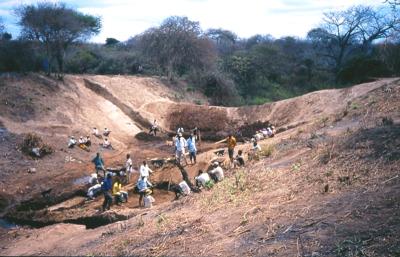
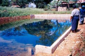
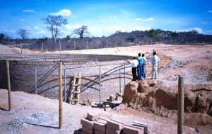
The photo shows the inflow channel to a charco dam seen in the background.
Usually, inflow channels have some logs laid across the floor of the inflow channel functioning as steps and silt traps to prevent the water reservoir from being silted up.
Charco dams are usually excavated manually by individuals near their homesteads for watering livestock.
The water may also be used for some domestic purposes, if it is boiled or treated by the Sun’s UV rays in transparent bottles (SODIS).
Farmers dig their ponds during dry seasons and enlarge them every year, until the owner is satisfied with the capacity of his dam.
The size of Charco dams depend on the following factors:
1) A farmer’s financial capacity to hire labourers to assist him excavating.
2) The expected volume of runoff water from the catchment.
3) The area available for constructing the pond.
4) The soil type.
Hillside dams are small earth dams with curved walls built on hillsides and sloping land are the simplest and second cheapest earth dams to locate, design, construct and maintain.

Suitable sites for hillside dams can be found on almost any sloping land that produces rainwater runoff.
The catchment can include roads, compounds, roofs, agricultural land and rock outcrops.
To avoid contamination of the water, there should not be any pollution sources, such as drainage from villages, slaughterhouses, latrines, rubbish pits, cattle dips, etc. in the catchment area.
Naturally, the best soil type for constructing a water reservoir should have a high content of clay. However, soil types other than the clayey type can also be used, although some seepage may occur downstream.
Despite seepage being considered as wasted water, it can be turned into an advantage such as; facilitating clean water in a hand-dug well that can be used for domestic water, watering livestock, garden irrigation, making burnt bricks, a wood lot, etc.
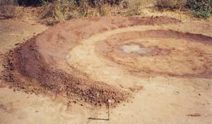
The curved heap of soil, shown above, will become the dam wall, while the excavated pit will be the water reservoir.
The size of the dam wall and its reservoir depends on the capacity to remove soil from the reservoir and placing it on the dam wall.
The gradient (slope) of the sides of the dam wall should be 2:1, which is 2 m width for every 1m of height.

An earth dam built in a valley is the cheapest way to create water storage, because the excavation work is less than for Charco dams and hillside dams. However, the gain in cost per volume can be lost overnight by flooding from one heavy thunderstorm or shower, which, unfortunately seem to be bigger and further apart every year.
The washout of a dam wall can be very serious and endanger both lives and property.
For this reason experienced technical help should always be sought for the design and construction of valley dams which might present a possible threat to downstream households.
Desert locust situation update
Credit:FAO Locust Watch


Three hot-spots of threatening locust activity
The current situation remains extremely alarming in three main areas.
(1) In the Horn of Africa, the worst affected area, there is an unprecedented threat to food security and livelihoods as swarms increase in Ethiopia and Somalia and continue to move south to Kenya where they have spread to 14 northern, central and southwest counties, reaching within 200 km of northeast Uganda and southeast South Sudan. Some swarms have already laid eggs and hatching is almost certainly underway. Swarms have also entered the Rift Valley in Ethiopia. Aerial and ground operations are in progress but remain insufficient. Breeding during February will cause a further increase with numerous hopper bands in all three countries. Some swarms may still reach Uganda and South Sudan in the coming days.
(2) Locust infestations continue to grow along both sides of the Red Sea where numerous hopper groups, bands and adult groups are forming. A swarm formed on the coast near the Sudan/Egypt border, swarms have laid near the Sudan/Eritrea border, and formed on the coast of Yemen, some of which have moved into the central highlands and to adjacent areas in southwest Saudi Arabia. At least one swarm appeared on the southern coast of Eritrea. Several swarms, presumably from the Indo-Pakistan border area, recently arrived on the eastern coast of Oman and moved south to Yemen.
(3) In southwest Asia, heavy rains on the southern coast of Iran where swarms were laying eggs, which should allow favourable conditions for two generations of breeding that could cause a considerable increase in locust numbers. Residual adult groups and swarms are still present along both sides of the Indo-Pakistan border while some swarms have moved into adjacent areas to the north.
Credits: Biovision-Infonet
Credits: Biovision-Infonet
Water from road catchments should not be used for domestic consumption because the water from murram and dirt roads contains dung and other pollutants, while water from tarmac roads contains tar which is harmful to peoples’ health.
Water for domestic use should be collected from either roofs, rocks or drawn from shallow ground water by means of hand-dug wells or hand-drilled boreholes.

Roof catchments for domestic water can be as cheap and simple as the photo on the left shows.
A sheet of metal or of polythene or a length of split Bamboo or Sisal pole is tied to the roof.
A rope hangs from the gutter to facilitate rainwater running along the rope into a 20 litres jerry can on the ground.
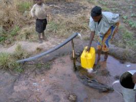
Plastic jerrycans play a very important role in rural water supply because nearly all domestic water is transported from the water sources to the homesteads in jerrycans.
Many women in dry areas have to carry one full jerry can of 20 litres of water, which is equal to 20 kg, on their back every second day.
In addition the women must also walk up to 10 km with the empty jerry can from the homestead to the water source which is usually in a riverbed.
They must also wait at the riverbed until it is their turn to fill their jerry cans with the water that seeps slowly into the waterholes they have scooped out of the sand.
They must walk 10 km up hill with the 20 kg jerry can because riverbeds are always in valleys.
At home they must ration the 20 litres of water to be sufficient for 2 days consumption because no woman has the stamina to fetch water from 10 km away every day, while also taking care of her children, livestock and homestead.

Where water has to be fetched from sources further away than 10 km a donkey has to be purchased.
A donkey can carry 4 jerry cans of water for distances up to 30 km during a return trip taking 2 days.
In those dry areas the cost of a donkey is equal to the dowry for a wife. When the rain comes, the cost of a donkey decreases because water can be fetched nearby, while the cost of dowry increases because now manual labour is needed in the fields.

Nowadays, some people prefer bicycles to donkeys for fetching water because bicycles are cheaper and more versatile than donkeys, although a bicycle can only carry a maximum of 3 jerry cans which is 60 kg of water.

Jerry cans are expensive for rural communities, therefore jerry cans have to be repaired when they leak or get worn out.
Should a jerry can be worn out, the leakages and holes in it can be sealed by plastic strips melted over a fire.
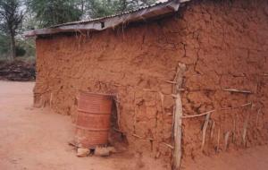
Most rural homesteads can afford an oil drum to harvest rainwater from the roof. Unfortunately, the lower part of oil drums corrodes. The oil drums are than discarded as scrap metal.
Note: Rusty and leaking oil drums can easily be repaired for the cost of half a bag of cement. The technique is simple.

Step 1: Mix a 1/8 of a bag of cement with coarse river sand in a ratio of 1 part of cement to 3 parts of river sand.
Step 2: Smear the mixture onto the inside of the oil drum in a 1cm layer and let it dry for a day.
Step 3: Next day apply a second coat of mortar 1:3 being 2 cm thick onto the interior of the drum and smoothen it.
Step 4: Within the same day, mix cement with water until it becomes a slurry called NIL and press it onto the interior plaster with a square steel trowel.
Step 5: Keep the oil drum under shade and sprinkle the plaster with water 3 times a day for a week, then fill it up with water.
Many people plaster their new oil-drums this way because the taste of the water drawn from drums coated with cement mortar has a nice sweet taste.
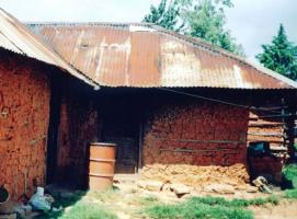
The image left shows a slightly larger roof catchment system with gutters fixed sloping along the full side of the roof.
A discharged oil-drum with a storage capacity of 210 litres is placed under the lowest point of the gutters where the rainwater will fall from the gutter.
Water tanks made of PVC for storage of rainwater can be bought from manufacturers but the cost of the tanks and the transport required to bring them to rural areas is high, although some manufacturers can give up to 50% discount.
It is often cheaper to use locally available materials and experienced builders to construct water tanks of concrete in situ (formwork), burnt bricks, soil compressed blocks, quarry blocks and concrete blocks reinforced with a spiral of barbed wire.
Water tanks can also be built of ferro-cement made of cement, coarse and clean river sand, chicken mesh, weld mesh and galvanized wires.
For any type and size of water tank these must always be circular, hemi-spherical or spherical (ball shaped) in order to distribute the internal pressure of water equally on the tank walls.
Square or rectangular tanks will always crack
Storage tanks should always be roofed with airtight covers to prevent mice, rats, lizards and snakes from entering, drowning and contaminating the water.
Airtight covers will also reduce evaporation losses in hot climates. Several types of roofs can be fitted onto tanks, although domes build of ferro-cement are the most durable.
The construction cost of the various types of materials and sizes of water tanks varies according to the availability of local materials and skills as well as the cost of transportation.
A budget should be prepared to compare the cost of constructing tanks with the cost of purchasing prefabricated water tanks.
Preferably, water should be extracted from storage tanks by gravity through a draw-off pipe of galvanized iron which is concreted into the foundation of tanks.
Although water can be drawn from tanks situated under the ground level, hereafter called ground tanks, by a bucket tied to a rope, or other types of simple water lifts and hand pumps, it is safer and easier to draw the water from a staircase leading down to a water tap and pipe which is concreted into the bottom of the ground tank.
Farmers and laymen have built several thousands of 5,000 litres water tanks using a technique called in situ which consists of compacting concrete reinforced with a spiral of barbed wire in between two cylindrical moulds made of either roofing sheets or old oil drums.
Local artisans, who can build houses, can usually also build water tanks of burnt bricks, soil compressed blocks, quarry blocks or concrete blocks. The volume of such tanks may vary in sizes from 3,000 litres to 30,000 litres.
It is important that the reinforcement of these tanks is made by wrapping a barbed wire, g 12.5, tightly around the outer side of the tank in a spiral spaced 5 cm at the lower half of the tank, where the greatest strength is needed, and 10 cm on the upper half.
Often it is much easier and cheaper to repair old and leaking water tanks and containers than buying or building new ones.

Water tanks made of galvanized iron sheets were popular some decades ago. Unfortunately, the bottom part of the tanks corroded and leaked after 5 to 10 years.
They were then considered useless and discharged as scrap metal. These corroded and leaking water tanks can be repaired easily.

The technique is as follows:
Step 1 Small holes are punched in the wall for every 15 cm or so using a nail and a hammer.
Step 2 Binding wire is cut in lengths of about 20 cm and bent in a U shape. One person puts the two ends of a U bent wire into two punched holes situated near each other.
Step 3 A second person presses chicken mesh against the wall and uses the two ends of the U wire to tie to chicken mesh tightly against the wall. Thereafter chicken mesh is laid on the floor of tank.
Step 4 Cement can now be mixed with clean river sand in a ratio of 1 part cement to 3 parts sand and some water. This mortar is then thrown onto the chicken mesh in a layer of about 1 cm thick.
Step 5 The next day another coat of mortar is added until all binding wires and chicken mesh are covered with mortar. Within the same day, cement slurry (NIL) is pressed onto the moist plaster with a square steel trowel for water proofing. The outside of the tank can be painted with a weatherproof paint made of 1 part cement to 10 parts of lime mixed with water.

Problem: Many tanks built of masonry leak water through the joint where the wall joins the foundation.
Reason: The reasons are either insufficient reinforcement, poor mixture of mortar or lack of cleanliness when the joint was made.
Remedy: The joint can be made watertight by cleaning the joint, adding more reinforcement and making an apron on both sides of the joint.
Step 1 Drain all water out of the tank and clean the floor and the foundation on the outer side of the tank.
Step 2 Chisel a groove, about 3 cm x 3 cm, all around the joint on both the interior and external sides of the tank.
Step 3 Roughen a 15 cm wide stretch of the foundation on both sides of the joint. Clean the joint and the roughened surface with plenty of water.
Step 3 Wrap 5 rounds of barbed wire tightly around the tank in the external groove.
Step 4 Compact mortar 1:3 into the external and internal grooves with a piece of timber.
Step 5 Compact a 15 cm wide and 10 cm high apron over the external and internal grooves.


Problem: Water leaks through cracks in the foundation.
Reason: Soft soil under the foundation, insufficient reinforcement, poor mixture of concrete or improper curing.
Remedy: The leakage can be sealed by constructing a new foundation onto the old cracked foundation.
Step 1 Drain all water out of the tank and clean the floor.
Step 2 Fill all cracks with bitumen paste
Step 3 Cut sheets of weld mesh to fit the foundation. All overlaps must be at least 20 cm and tied together with binding wire for every 10 cm.
Step 4 Mix concrete with 1 part cement to 3 parts river sand and 3 parts of crushed stones (1:3:3). Compact a 7 cm thick layer of concrete onto the old foundation.
Step 5 Lay the weld mesh on the concrete in the tank.
Step 6 Compact a second layer of 7 cm concrete onto the weld mesh in the tank.
Step 7 Compact a 1 cm thick layer of mortar 1:3 onto the concrete. Smoothen the plaster and press a coat of NIL onto the plaster the same day.
Step 8 The next day, compact a rounded apron into the joint between the new foundation and the wall.
Step 9 Keep the foundation moist and under shade for 3 weeks

Problem: Water leaks through the wall of a water tank, although the wall has no cracks.
Reason: The wall is leaking due to porosity caused by either a mortar mixture with insufficient cement, insufficient curing or poor workmanship.
Remedy: The wall can be sealed by replacing the porous parts with mortar 1:3 and with NIL. Should the wall still leak after that treatment, the interior of the tank should be coated with a water proofer.
Step 1 Drain all water out of the tank and clean its interior
Step 2 Chisel away the porous parts of the interior wall.
Step 3 Clean the chiseled parts with water and throw dry cement onto the watered parts of the wall.
Step 4 Mix mortar of 1:3 and throw a thin layer of it onto the watered parts of the wall.
Step 5 Step 5 Next day, fill up the coated parts with mortar 1:3 and apply NIL with a square steel trowel. Keep the plastered parts moist under shade for 3 weeks, and then fill the tank with water.
Step 6 Should the tank still leak, its internal side has to be painted with a water proofer, such as swimming pool paint, non-toxic bitumen, oil paint or 1 part of cement with 10 parts of lime mixed with water.

Problem: Water leaks through cracks and fissures in the wall of a water tank.
Reason: Vertical cracks are due to insufficient horizontal reinforcement and/or incorrect joining of bricks and blocks. Horizontal cracks are due to incorrect joining between the horizontal courses between bricks and blocks.
Remedy: Build a new tank on the outside of the cracked tank by wrapping reinforcement mesh or wire around the tank and plaster it.
Step 1 Drain all water out of the tank and clean it.
Step 2 Chisel off any loose part on the external side of the tank wall
Step 3 Tie sheets of weld mesh together with binding wire and wrap them tightly around the tank and plaster the outside of the tank with 3 cm of plaster 1:3. Alternatively, wrap chicken mesh tightly around the cracked tank after which a spiral of barbed wire, gauge 12.5 is wrapped tightly around the chicken mesh with a spacing of 5 cm at the lower half of the tank and 10 cm apart on the upper part of the tank. Thereafter plaster the outside of the tank with 3 cm of plaster 1:3.and keep it moist under shade for 3 weeks.Paint the tank with a weather proof paint made of 1 part cement to 10 parts of lime mixed with water.

Farmers and laymen have built several thousands of 5,000 litres water tanks using a technique called in situ which consists of compacting concrete reinforced with a spiral of barbed wire in between two cylindrical moulds made of either roofing sheets or old oil drums.
Local artisans, who can build houses, can usually also build water tanks of burnt bricks, soil compressed blocks, quarry blocks or concrete blocks. The volume of such tanks may vary in sizes from 3,000 litres to 30,000 litres.
It is important that the reinforcement of these tanks is made by wrapping a barbed wire, g 12.5, tightly around the outer side of the tank in a spiral spaced 5 cm at the lower half of the tank, where the greatest strength is needed, and 10 cm on the upper half.
Credits: Biovision-Infonet
There are two main types of water tanks, namely:
1) Ground tanks that are built below the ground level. These are mainly used for storage of dirty run-off water from roads and compounds. Ground tanks can also be used as storage for clean domestic water if the tanks are roofed and connected to gutters attached to roofs or rocks.
2) Surface tanks standing on the ground level which are cylindrical and mainly used for storage of run-off water from roofs and rocks.

Ground tanks should always be designed as either hemi-spherical (half ball shape) or cylindrical because those shapes equalize the pressure of water and soil whether the tanks are full or empty.
This hemi-spherical tank (see image above) built of burnt bricks reinforced with barbed wire and chicken mesh is for roof catchment of domestic water.
This photo shows a rectangular tank for fish farming in Myanmar. Two sides of the tank caved in when the tank was emptied of water due to pressure from the soil.
Note: Water tanks should never be designed using square and rectangular shapes because they will collapse due to the uneven pressure of water and soil whether the tanks are full or empty.
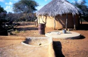
A traditional underground cylindrical water tank at a homestead in Botswana from which water is drawn by a bucket tied to a rope.
The catchment area for the tank is the threshing floor for millet and sorghum, which is made water repellant with a coat of cow dung.
The floor slopes towards a silt trap where a plastic bottle prevents mice and lizards entering the tank.

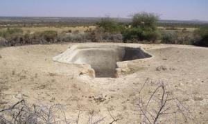
A simple and cheap ground tank can be made by excavating a cylindrical hole and plastering it with mortar cement onto chicken mesh (Ferro-cement).
A series of two hemi-spherical ground tanks built of burned bricks collect and store run-off water from a school compound for irrigation of a tree nursery and small irrigation garden.
A roof catchment tank can be seen at the school building. It provides drinking water for the pupils.
The berkad ground tanks for watering livestock in Somaliland are banned by the government because of environmental degradation due to over-grazing caused by insufficient fodder.
Moreover, most of the rectangular berkads must be repaired every year due pressure from the soil when the tanks are empty.

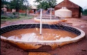
In Kenya, the rectangular berkad was redesigned to be oval-shaped and roofed with barbed wire covered with thorny Bougainvillea climbers, two large silt traps and a staircase made of concrete for drawing water by hand in buckets.
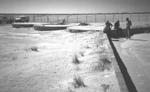
The hard sandy surface of the Kalahari Desert in Botswana is used as catchment area for these three large cylindrical water tanks, which provide domestic water for the San people (Bushmen).
In the dry central plateau of Tanzania, a 500 m3 cylindrical water tank, made of reinforced concrete, was built to collect run-off water from a 2 sq.km catchment area. The water is for domestic use by the communities living nearby.
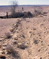
This ground catchment tank is known as “King David’s Well” in the Negev Desert of Israel and it is estimated to be about 2,500 years old.
The conical ground tank is lined with lime stones mortared together with lime mortar.
The catchment area is a large stony hill from where the annual rainfall of 100 mm falling in the month of December is diverted into the tank by long trenches sloping upwards from the tank.